Monday, October 14, 2019

Adding the Amazfit Bip


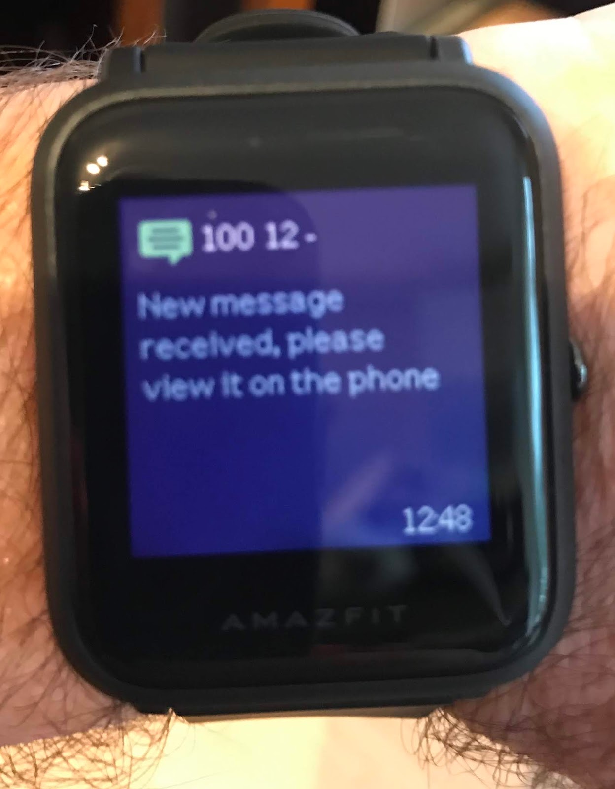
Here's the Amazfit Bip Watch.  Example of the regular watch face and notifications.  The notification is, estimate 100 mg/dl, 80 mg/dl in 12 minutes, falling.

This continues to be a battle to stay ahead of product obsolescence.  My Amazfit Band died after 10 months.  It would no longer charge.  The root problem was most likely that it was no longer waterproof.  The thing basically fell apart in my hand while I was trying to attach the charger.

Potentially tricky using the Amazfit products now.  The new firmware requires a server generated key.  So, you have to activate the watch with your phone, using the MI app.  But don't let the app update your firmware, when it starts to do that, close the app.  Then go to Arduino and do the pairing as you normally(how much of this is normal?) would.  A shame, there's allot of interesting functionality on this watch, but I can't use it.

On deck, I'm messing around with the Ticwatch, which is Wear OS, which used to be Android Wear.  This isn't going well.  Like my previous battle with Android Wear, I can't keep bluetooth up for more that 6 hours, at some point the watch decides it's inactive and shuts everything down.  You can't restart bluetooth without rebooting the watch.  On top of that, ambient mode changed, and the watch is only good for about 11 hours.  It's also clunky and huge.  The cool thing with this project is calibration can be performed on the watch.  Almost back to the functionality I had on the Pebble Round... So close, yet so far.

---10/15/2019 Update----
Way to many features on this watch to not risk letting it update it's firmware.  Did not remove my pairing, so good to go.

---10/19/2019
Continue to be amazed with this watch.  Battery is going to last nearly 2 weeks.  Using the GPS on runs, integrates with Strava.  I'll probably ditch the Vivosmart in the near future, although I do like the Garmin software.  Updated the fonts to Bold, can easily read it now.  Don't think I'll be wasting anymore of my time on Wear OS/Android Wear.  Why deal with a wearable that requires daily charging?

Monday, September 30, 2019

Joys of iPhone Updates

The recent iPhone update really screwed with my iPhone app.  Have to renew my Dev license and see what's up.

App works if I leave it open, and close the phone.  
Sometimes, it appears that is goes to sleep, no glucose readings are evaluated, until I open the phone, then it instantly reconnects and pulls in a value.  Maybe I backgrounded the app in this case.

It's really bad at discovering the bluetooth device now.  It will scan for about a minute and then shut down.  I don't think it will connect at all from the background.

And all of this behavior varies.  Best bet is to keep it wide open, with the screen on, if I need to use it.

Thursday, September 19, 2019

Wahoo Elemnt as a CGMS

Or really, any BLE compatible HR Monitor.


Was doing a mountain bike race this weekend, and was once again reminded of how I'd like glucose on a display I could easily see.  The watches, fitness bands etc.  don't show up very well in bright daylight.

This is something I'd wanted to do with ANT+ years ago, but there wasn't any convenient dev board, and I'm not sure if I ever worked out how to appear as a HR Sensor.

This is much easier to do with bluetooth.  Since I'm using the Adafruit NRF Feather, it was easy to lift their sample code for the custom_hrm.  And you see it above.  I can now track my blood sugar from my handlebars, 169 in this case.

9/30/2019 This is good up to 229, then it wraps around and/or doesn't reliably show a number.

Wednesday, January 23, 2019

Adding the Amazfit Cor


So, I use reading glasses.  The MI Band 2 is hard to see at times.  In the middle of the night and while driving, the notification will go away before I can focus.

According to Gadgetbridge, the Amazfit Cor uses the same "OS" as the MI, so I picked one up.  I can definitely read the display. 

Added bonus, you can go to the notification screen and review the past 10 messages, which is nice since the MI just erases them after 2 seconds.

Wednesday, November 21, 2018

Standalone fitness band

I now have a MI Band displaying Glucose without a paired iPhone.  You just need the iPhone to push the calibration details to the device.

Lots to do here:
  1. Get the CC2500 code working on the Feather (SPI protocol)
  2. Get central to MI communication working.  Adapt what people have done in Python, to work on the Arduino.  See https://medium.com/machine-learning-world/how-i-hacked-xiaomi-miband-2-to-control-it-from-linux-a5bd2f36d3ad for a start.
  3. Also code the peripheral side so the feather can communicate with an iPhone, pushing the isig and retrieving the slope/intercept.
  4. Build the circuit
  5. Print a container
  6. Get a reasonable battery life


First started with everything on a breadboard, Feather NRF52 and a CC2500 board on a breakout.

Getting the CC2500 working wasn't too bad.  Only some question as the where the Chip Select/Slave Select pin was on the feather.  I recently found some mention that it was A8.  My code has it on A3, since I couldn't find where it was mapped initially.

Central to MI took allot of time, knew that going in.  To really understand what was going on, I had to get that working first in Python on a Raspberry PI.  This guy had a great script: https://github.com/vshymanskyy/miband2-python-test .  

Hardest part of the conversion is doing the AES 128 ECB encryption for the key exchange with the MI.  This reminded me of communicating with the Dexcom back at the start of this blog where you had to calculate a CRC.  In either case, there are lots of methods available, and lots of public implementations that may or may not work.  I probably tried 10...  In the end this did the trick.
Finally, very little out there for Central samples.

The peripheral side of things was tricky for me because of the way the iPhone caches BLE Characteristics.  For a couple of days, I could enumerate my new characteristics from Linux, but the phone, and xCode and light blue wouldn't show anything.  Turns out you need to restart your phone.
Modified my iPhone app to work with the new device and finally display the dexcom transmitter battery level.

With that, squeezed together a circuit:


I may do a PCB in the future, I don't trust the wires.  Also, would have been allot easier.  The connections on the CC2500 are very small, not easy to solder to.

And printed another box, 2.25 x 1.6 x 0.4 (inches)


First week, could only get 12 hours on a charge.  That works out to 9 ma/hr.  Broke out the current measuring apparatus and started watching things.  My initial central only sketch was hitting 9ma on pairing then settling down to 3ma, but the full code base was fluctuating between 9ma and 13ma after the first CC2500 receive event and refusing to drop below 9ma.  Hmm.
Did some desperation googling, found a Nordic post on how some low level errors will prevent the Microcontroller from ever entering low power mode.  A note here, you can run the NRF52 in debug mode and get some extra detail in the serial monitor.  In this case, I noticed a few unhandled error messages, that don't crash the micro, but they prevent low power mode.  An example of one, would be attempting to connect to a peripheral after you've already established a connection.  The central examples that come with the feather are prone to this...  Fixed these issues, battery life is now 3 ma/hr or lower.  Codewise, doesn't appear that waitForEvent has any impact on battery, delay does.
99% of the time, the device is at 2.5ma, the CC2500 uses 27ma for 2 seconds every 5 minutes, and communication with the MI costs 9ma for a few seconds every 5 minutes or much much less, since I don't send value every 5 minutes unless the current glucose level is a concern.

Nothing to be gained space wise, so no point going to a smaller battery, done.

Display is a bit small, and the regular notifications are cleared very quickly.  The real alerts vibrate until dismissed so you'll get to read those without issue.  Like the VivoSmart, I'm not displaying glucose in the traditional manner.  Example, if my blood sugar is in range, and not at risk of being high or low in the foreseeable future, nothing is sent to the band.  If I'm really paranoid I can always check on the iPhone.  Battery life on the MI is weeks.  You can also still connect to MI Fit to get your step counts, although I don't let it pair.

See my github for the code.  


Tuesday, October 23, 2018

BLE Dual Mode finally coming up

Started poking around at my many year old (and mostly useless) BLE Nano's.  Turns out they're supposed to be able to support S130.  After a few hours, gave up, and finally threw them out so I won't waste more time on them next year.

A little more googling, turns out Adafruit has a feather that does S130 (actually S132 in this case).
So...

Add this doo dad:

And I have a phone free CGMS, again.

So, with the Mi Band I can get custom notifications to it from Xcode, you can also send a notification that will make it buzz until you acknowledge, very cool.  Just have to convert all the Xcode for pairing etc. to Arduino land.  More on that later, much later.

Onto the hardware.  The feather can serve as Central to the Mi Band (ie. masquerade as a phone) and as peripheral to the iPhone.  It can be a casual relationship with the iPhone, where the phone is just a front end for calibrations, everything else lives on the feather, no phone, no problem.

Tuesday, September 4, 2018

Battery Replacement

After many years, I've finally managed to replace the batteries in a G4 transmitter.
Dying batteries is what compelled me to figure out the RF protocol years ago.  At the time my transmitter died just after 6 months, so a replacement wasn't covered by insurance.  There never was a warning from the device.

Over the last few weeks I've watched the battery level run down to where it dipped from 212 to 210.  Allegedly the point at which a Dexcom receiver will tell you to order another.  Was still functioning at 212/210, but range seemed diminished and definitely noisier.  I finally pulled it when it gave me a reading that was half of reality (something like 90 for a 175).

Finished result.  Took allot to get here.  Used Devcon 5 minute epoxy and an epoxy thickener that I had around from some past boat repair.  The Devcon 2 barrel syringe works really well, I've tried other brands that just didn't mix well, and the epoxy never cured.

I use a rasp and a really small router bit in a Dremel to get the batteries out.  The batteries are spot welded on the top and bottom.  I like to grind through the battery so I can get a screwdriver in it and lever it up a bit, then push a screwdriver in from the bottom and carefully push the tab away.  Repeat for the top.


I followed the iFixit guide by Joern.  The tricky part for me was getting sufficient contact between the top tabs and the battery.  Super glue just doesn't work.  I also tried something called "Wire Glue", carbon powder in a paint like substance, conductive.  That also didn't do the trick.  Only thing that works for me is soldering the top tabs to the battery.  Use a faceshield, too much heat and the batteries explode, I ruined a few.  I put a couple of drops of superglue around the bottom edges of the battery, then use my drill press to gently press and hold it in place for 5 minutes.  I'm surprised it holds as well as it does, you don't need to wait 24 hours for full strength.

To date, I've soldered the battery after gluing it.  Might be better to solder it in place, pop it up, and then glue it.  My solder job on this is horrible, but it makes the connection.  I can do a beautiful job soldering CR2032's, but these tiny batteries, not so much.  Sand the top of the battery, carefully sand the tab the best you can, maybe try tinning the battery top before soldering the tab on.  Lastly, glue it.
Also, hold the tab against the top of the battery while soldering, something thin and metal works, too much metal will work as a heat sink though.

You can measure the voltage on the bottom of the transmitter using the two pins.  You should see something around 0.270 mv.  This will vary depending on what kind of voltmeter you have (cheap or legit...).  Ideally, measure the voltage before you take the transmitter apart so you know what to shoot for.  The iFixit guide was 0.09 mv.  

Initially I kept getting high 100's, indicating that only one battery was really connected.  Soldering did the trick.

The next issue is batteries.  I ordered SR1120's, the battery dexcom uses.  I had a pair of Maxell and I purchased a 5-pack of no brands off of Amazon.  These were way too cheap, but I didn't realize why at the time.  I promptly blew up the Maxell's trying to solder them, then moved onto the cheapies.  These worked.  But the battery level reported by the firmware was 198 (you want 215 216).  Surprisingly this worked fine, signal was a bit week, but it was accurate.  Turns out, I bought Alkaline not Silver Oxide.  Would have been lucky to get 3 months I think.

Finally, I replaced the batteries a second time with Energizer 390/389 batteries and got the 216 level that you'd expect from a new transmitter.  These are slightly larger, hopefully I'll get 15 months before I have to repeat this exercise.

Lastly, I used duck tape around the transmitter to make a "dam", then I poured the epoxy in.
Once that set, it was easy to sand it down to something that looks very close to original.